CDR Guidelines – Engineering Associate Career Episode Sample
Having Trouble Writing your Career Episode Report ?
Get in Touch with Our Writers to get the Help you Need and Avoid Possible Rejection!
Or talk to our writers at +61 481 614 316 / +61 483 968 416
Career Episode Report Example for Engineering Associate
A competency demonstration report (CDR) requires migrant engineers applying to Engineers Australia to write three career episode reports (CERs). Career Episode Report for Engineers Australia gives detailed information on technical and other skills an engineer applied to the project described. You must demonstrate your professional competencies in your career episodes. Here is a writing style for a Career Episode Report Example for Engineering Associate.
INTRODUCTION
CE 1.1
I have demonstrated about my project titled “Simple Timer Switching Circuit” as a requirement for this career episode. I have done this project as a requirement for my Diploma in Electrical Engineering and submitted to the Department of Electrical Engineering of XXX (University Name and location). This project was started on… and completed on… under the supervision and direction of my project supervisor …………
BACKGROUND
CE 1.2
The touch ON and OFF switches circuit is the simple circuit that works with the use of 555 IC timer device. The IC timer has 8 pins which are connected to the touch plates as per the default properties of the 555 Timer IC pins. For the simplicity of the functioning of the device, this simple touch circuit can be used to turn ON and OFF any devices by the simple touch on the touch plates. When we touch on the touch ON plate of the circuit, the device gets activated, and when we touch on the touch OFF plate of the circuit, the device gets deactivated.
CE 1.3
The major objectives associated with the project are:
To design a simple touch ON and OFF circuit with the use of 555 Timer IC.
To analyze the working mechanism of the touch circuit with the copper touch plates.
CE 1.4
This project was an individual academic project, and thus there was no involvement of any other teammates for this project. However, I took the guidance and supervision of the project supervisor for the project. The organizational with the illustration of my position in the project is shown below:
CE 1.5
I was the sole individual responsible for the completion of the project. The major responsibilities that I performed for this project were:
Accumulate the necessary information for the completion of this project through the literature review of the other projects and reference books
Make the circuit diagram of the touch circuit with the use of 555 timer IC
Select the necessary components for the circuit design
Select the copper boards as the touch plates required as the touch sensor for the device operation
Connect all the components as per the default pin configuration of 555 Timer IC
Supply the power to the circuit and analyzed the working mechanism with the ON and OFF of the touch circuit
Submit the progress report of the project to the supervisor for the review
PERSONAL ENGINEERING ACTIVITY
CE 1.6
This project was an individual academic project. I was the single individual responsible for the completion of this project. Thus, before initiating the designing task of the project, I referred the reference books from the library and some videos on the internet sources regarding the project ideas and information. Then, I organized the gained information in a systematic way to make the project schedule and carried out the real task of the project.
CE 1.7
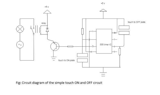
Firstly, I made the circuit diagram of the required touch on and off switch circuit. The circuit diagram is below: (ANZSCO code 233311 task 2)
CE 1.8
After the completion of the required design of the switch circuit using touch plates, I analyzed and selected the required components for the project. The selected components are listed below: (ANZSCO code 233311 task 2)
555 Timer IC
5V relay module
2 MΩ resistor
Bulb
Breadboard
CE 1.9
As the components were selected, the next task was the making of the touch plates for the project as they were the vital part of the project design. I used two small pieces of copper-clad boards of required dimension. Then, I made the groove in the middle of the used copper board without breaking it completely. I did this so that there will be two halves on the board required for the project. (ANZSCO code 233311 tasks 3)
CE 1.10
The next phase of the project was the task of the circuit design of the touch on and off switch circuit. For this, I connected the GND, VCC and RST pins of the used 555 Timer IC which are the pins 1, 8 and 4 respectively of timer IC to the GND and 5V respectively. Similarly, high MΩ resistor was connected to pin 2 and low MΩ resistor to the pin 6 of the timer IC. In the remaining pins 2 and 6, I connected two touch plates as per the circuit diagram. I connected the touch plates in such a way that one end of touch ON plate is connected to pin 2 and another end to GND. Likewise, one end of touch OFF plate is connected to pin 6 and another end to a 5V source. (ANZSCO code 233311 tasks 3)
CE 1.11
After the completion of the circuit connection with the pins of the timer IC, I applied the power supply to the circuit and observed the working of the project. The basic principle is that I had to touch on the ON plate for turning on the device and touch on the OFF plate for turning off the device. Firstly, I touched on the ON plate. As a result, the voltage at pin 2 of IC became low, and thus the pin 3 became high. Then, the transistor will turn on as this pin 3 is connected to the relay module used in the circuit. Finally, the device gets switched ON.
Next, I touched on the OFF plate of the circuit, then pin 6 of the timer IC was supplied with 5V for some duration and thus, the pin 3 which is the output pin became low. As a result, the connected transistor gets turned off and thus the relay of the circuit. Finally, the device gets switched OFF. (ANZSCO code 233311 task 5)
CE 1.12
I observed that the device worked as a flip-flop device. When the touch ON plate is pressed, the relay gets activated and thus the device. When the touch OFF plate is pressed, the relay gets deactivated and thus the device.
CE 1.12
I observed that the device worked as a flip-flop device. When the touch ON plate is pressed, the relay gets activated and thus the device. When the touch OFF plate is pressed, the relay gets deactivated and thus the device.
CE 1.13
Initially, during the connection of the pins of 555 Timer IC with the components and the touch plates, I had connected the pins with the wrong configuration so, the circuit didn’t function. For easing this issue, I referred the datasheet for the pin configuration and connected the pins with proper configuration. (ANZSCO code 233311 task 4)
Another problem that I faced during the circuit operation was that sometimes the circuit triggered itself without touching the touch plates. To solve this issue, I reduced the sensitivity of the circuit by the reduction of the resistance value of the resistor connected to the touch on the plate.
CE 1.14
I used two small pieces of copper clad boards as the requirement for touch plates used in the circuit. (ANZSCO code 233311 task 3)
CE 1.15
This project about the design of the simple touch ON and OFF circuit with the use of 555 Timer IC was done as an individual project. I performed all the tasks associated with the project and ensured that the project was completed within a limited time. For the difficulties I faced on the project, I consulted with my project supervisor. His effective guidance and suggestions throughout the project were vital for my project completion with the achievement of the desired results. I also submitted the progress report of the project to the supervisor on a weekly basis. I maintained effective verbal and written communication with the supervisor throughout the entire project. (ANZSCO code 233311 task 5)
CE 1.16
I ensured that the project work was carried out as per the associated norms and ethics of the project. I followed the regulations of the Electrical Engineering Department and the university effectively while performing this project task. During the interaction with the supervisor, I used to present myself in an organized and disciplined manner and followed his guidance with full respect. Likewise, I didn’t dispute with the supervisor or any persons while performing the project and carried out the project in a peaceful and safe environment. I followed the datasheets of 555 Timer IC while performing the pin configuration on the circuit. The components used in the circuit were standard components that were approved to use in the country. (ANZSCO code 233311 task 4).
SUMMARY
CE 1.17
Finally, the project about the design of the simple touch ON and OFF switches circuit with the use of 555 Timer IC was complete within the limited time with my dedication and guidance of the supervisor. This project made use of the relay module and copper plates as the touch plates required for the project. This circuit works as per the basic functionality of the configuration of the pins of 555 Timer IC. The proposed design circuit can be used to turn ON and OFF any device by simply touching the touch plates. Overall, this project is simple to design and economical as only a few components are used in the design of the circuit.
Other Career Episode Report Samples


CDR Report Guidelines
CPD
Career Episodes
Summary Statement
Make Sure your Report gets Accepted by the ACS
Instead of wasting your time and money with incompetent agencies, contact us for your guaranteed success. Our writers will make sure the results are refined, proofread, and plagiarism free. We are giving Free Consultation for our clients.
Pricing of Complete CDR Report Writing
We provide our complete CDR Writing service on the basis of your urgency level and prices respectively. There are currently three types of service that you can purchase which are shown below.
15 days plan
AUD
799
-
3 Career Episodes
-
Summary Statement
-
Plagiarism Check
-
Correction Limit (3 times)
-
Speak with the Writer
-
PR procedure guidance
-
Full Refund
10 days plan
AUD
999
-
3 Career Episodes
-
Summary Statement
-
Plagiarism Check
-
Correction Limit (6 times)
-
Speak with the Writer
-
PR procedure guidance
-
Full Refund
7 days plan
AUD
1299
-
3 Career Episodes
-
Summary Statement
-
Plagiarism Check
-
Correction Limit
-
Speak with the Writer
-
PR procedure guidance
-
Full Refund
Royal Package
AUD
2999
-
3 Career Episodes
-
Summary Statement
-
Plagiarism Check
-
Correction Limit
-
Speak with the Writer
-
PR procedure guidance
-
Full Refund
1000s of Satisfied Customers
Our Services receive great response and guarantee Success. Few client feedbacks are shown below.
Join the Hundreds of Skilled Migrants Who’ve Secured Approval
We assist skilled migrants in achieving success through professional guidance and skill assessment documents. From CDRs, RPLs, ACS skill assessments, and other migration-related documents, we ensure that your application meets the criteria for success.

On-time Delivery

Official Standards Compliance

Expert Technical Review
Feeling Curious? Get Your Skills Assessment Approved, Call Us Now! +61 481 614 316 / +61 468 072 490
We are here to answer all your queries and provide you the best service. Feel free to contact our writers for your concerns.